You must be signed in to read the rest of this article.
Registration on CDEWorld is free. You may also login to CDEWorld with your DentalAegis.com account.
Placement of dental implants requires planning that carefully considers the ultimate restorative results that are desired. This is true even in uncomplicated cases requiring a single implant. Placing an implant without giving thought to the final restoration is analogous to starting construction of a building without knowing what the final architectural form will be.
This article reviews the steps necessary to evaluate and prepare for placement of a single implant, a situation that can occur frequently in the private general practice. Design and fabrication of the radiographic and surgical guides necessary to ensure predictable implant placement are discussed, along with current choices for restoration retention.
Opinions about the best way to retain implant-supported restorations have shifted throughout the course of modern dental implant history. In the earliest days, when prostheses frequently had to be removed in order to remove failing implants, screw retention was regarded as clearly superior.1 But implant survival rates climbed quickly as understanding of the biomechanics of dental implants grew, better products appeared on the market, and techniques for placing and restoring implants evolved. With success rates predictably reaching 90% and above, concerns about occlusion and esthetics moved to the forefront, and cement retention gained proponents.2 They cited not only the improved esthetic results achievable with cemented prostheses but also their relative simplicity, avoidance of problems with screw loosening, passivity of fit, better control of occlusion, and economy.3 More recently, new concerns about cemented restorations have arisen due to the complications of residual cement that was not removed from the subgingival areas once the cement set. Cemented restorations can be used successfully in the posterior regions of the mouth where the cement margin is 2 mm to 3 mm above the gingival tissues to facilitate cement removal. Periodontal complications with inflammation and crestal bone loss have been documented with residual cement remaining in the gingival sulcus.4,5
A 2012 literature review of peer-reviewed English-language literature comparing cement- versus screw-retained restorations found that each method has certain advantages and disadvantages; however, there are some clinical situations in which is it better to select one method over the other.6 Moreover, a third hybrid approach to retention, sometimes called the “screwmentable” restoration, has been introduced7 and has gradually gained proponents. Case reports illustrating each of these three approaches will be presented, along with their indications.
Case Evaluation
A key to successful implant placement and restoration is to select cases that fall within the clinician’s areas of expertise. The patient’s medical history must be carefully reviewed, giving special consideration to individuals who are diabetic, heavy smokers, receiving treatment with bisphosphonates, or have recently received radiation therapy involving the head and/or neck. Comprehensive intra- and extraoral examinations are always recommended, as is a full dental charting. The gingival status of all remaining teeth should be evaluated, along with the temporomandibular joints, to identify any dysfunction of the stomatognathic system.
Accurate original diagnostic casts (alginate, simple alginate, or vinyl polysiloxane [VPS]) should be fabricated using the correct water/powder ratio. Such casts may be used later to create radiographic guides, or they may be duplicated—thus the need for accuracy in the first impression.
The diagnostic casts should then be mounted either with a facebow transfer or an accurate centric relation record. This is important in order to identify any supereruption of the teeth. Available interocclusal space should be evaluated with an eye to determining any changes that will be necessary in the vertical dimension of occlusion. Once the case is mounted, obtaining a diagnostic wax-up of the missing tooth can be invaluable. Either the laboratory can create a conventional wax-up, or a denture tooth can be set in the edentulous site. In articulation this will provide a buccolingual contour of the implant restoration to be placed later.
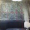
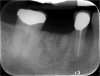
To obtain the maximum amount of information from the cone-beam computed tomography (CBCT) scan, a radiographic guide should first be fabricated. The periapical radiograph of the site where the tooth is absent can yield substantial insight into the approximate positioning that will be desirable for the implant(s). Figure 1 shows a case in which the patient wished to replace the missing right maxillary first and second molars with implant-supported restorations. The periapical radiograph revealed inflammation distal to the bicuspid root. In some cases, adjoining roots may impinge into the space to an even greater extent; it is important to avoid any perforation into the periodontal ligament.
The long vertical red line on the radiographic image has been placed roughly parallel to and approximately 1.5 mm from the bicuspid root. The mesiodistal width of the average molar is 10 mm; therefore, two horizontal lines, each 10 mm across, have been measured from the long vertical line. Dropping a vertical line through the midpoint of each 10 mm horizontal line segment provides an indication of the location of each implant. When making these sorts of calculations, it is important to consider the contact with any adjoining teeth. If a crown is bulbous or overcontoured, it may need to be adjusted by flattening the contours to obtain the necessary approximation. Lines corresponding to the calculations on the radiograph can then be drawn on the mounted cast. The buccolingual dimensions of the patient’s natural dentition on the opposite side of the arch can help to confirm the planning for the replacement crowns.
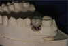
Once this preliminary implant-placement planning has been accomplished, the cast can be mounted on a surveyor (typically used for removable partial dentures). In this case, using a drill press, holes were made in the cast to indicate the location of the two implants, and guide pins were inserted in the holes. A radiographic guide that houses the guide pins was then fabricated. This can be accomplished using 0.5 mm biocryl material or an Omnivac shell. The patient will wear this radiographic guide when the CBCT scan is obtained. If a decision is made to adjust the angulation of the implant, the hole in the diagnostic cast can be re-prepared before fabrication of the surgical guide.
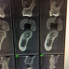
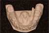
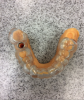
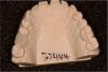
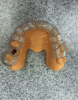
A second technique for fabricating the radiographic guide is to position silicone putty over the diagnostic wax-ups mounted on the cast and then create holes to expose the wax-ups (Figure 2). The putty is then transferred to the edentulous cast after the implant osteotomies have been drilled in it and the guide pins inserted. Light-body VPS is then inserted around the guide pins. When the patient wears the radiographic guide to the CBCT scanning, the scan will clearly show the position of the wax-up, its occlusal surface, and its buccolingual contours (Figure 3).
For even simple single-implant cases, the author highly recommends beginning with the type of workup described here in preparation for a CBCT scan. The radiographic guide is worn during the scanning; it provides information about the tooth position relative to the bone. The CBCT scan provides critical 3-dimensional (3D) information about the site. This includes anatomic landmarks such as the inferior alveolar nerve canal, from which a distance of at least 2 mm is recommended. The CBCT scan assists with determination of the final implant position.
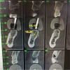
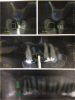
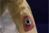
Figure 4 shows another case for which the guide post was embedded in the silicone putty. The outline of the tooth and the planned implant positioning can clearly be seen, along with the inferior alveolar nerve canal and a concavity on the lingual aspect of the molar. Measurements on the CBCT file show that the site width is about 10.38 mm, and the height above the inferior alveolar nerve canal is about 14 mm. Clearly, enough bone is present to accommodate an implant. But the question arises: should the angulation be changed slightly in light of the restorative plan? The diagnostic wax-up is the plan for the restorative implant crown. While the implant position in Figure 5 is acceptable for an initial approximation, it may be desirable to change it. For example, it may be decided to have the restoration be screw-retained. If this is the case, the screw access will need to be positioned not necessarily in the central fossa, but slightly more to the lingual.
If the bone were much straighter in this position, the implant could be placed a little straighter as well. But because of the bone configuration, angulating the implant slightly to the lingual is desirable.
Once the CBCT scanning with the radiographic guide has taken place and any changes to the implant position or angulation have been made, the next step is to fabricate a surgical guide in a Biostar or Omnivac-type machine using 2-mm thick biocryl material. The sleeve in the surgical guide endures accurate and precise positioning and angulation of the implant.
The following three cases illustrate creation of three different types of single-implant restorations using this kind of planning process.
Cement-Retained Restorations
Advantages that have been cited for cement-retained restorations include better esthetics for poorly positioned implants,8 more easily achieved passivity,9 better control of occlusion,2 easier placement (particularly in the posterior and/or cases with restricted mouth opening), and lower expense.10 Disadvantages include less retrievability, a greater need for interocclusal space,11 and the potential of iatrogenic retained cement.12
The following case illustrates use of a cement-retained single-implant restoration.
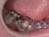
The patient wanted an implant-supported crown to restore the right mandibular first molar, which had been extracted after recurrent caries, endodontic treatment, and development of a periapical lesion. The site was grafted with bone grafting material and a biological membrane and allowed to heal for 6 months. A periapical radiograph was then taken (Figure 6), which showed the socket areas to be well condensed, with mature-looking bone. A CBCT scan was taken to facilitate implant-placement planning.
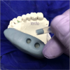
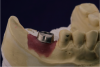
Two impressions were made: one to serve as a record of the edentulous site, and the second for use in making a stone diagnostic cast. The stone cast was scanned, and a stereolithographic model of the restoration was printed and mounted on the cast (Figure 7). Scan data from this was merged with the CBCT to enable 3D guided surgical planning. The location of the inferior alveolar nerve canal was identified, and an ample amount of bone above it was evident. A 12-mm-long, 4.8-mm-diameter implant was chosen for placement.
Based on this information, a CAD/CAM 3D surgical guide was printed (Figure 8). Fabrication of a full-arch surgical guide is highly recommended to provide maximum stability and retention during the surgery. The guide was tried in the patient’s mouth (Figure 9), and proper seating was confirmed.
A supracrestal subperiosteal flap extending from the bicuspid to the second molar was reflected, exposing the alveolar ridge. The implant was placed and allowed to heal, and the patient returned for the restorative phase of treatment. Because the implant placement was slightly to the facial, a decision was made to retain the restoration with cement. A custom platform-switched abutment was fabricated with the finish line at the gingival margin to facilitate cement removal.
When the patient returned for delivery of the definitive porcelain-fused-to-metal (PFM) crown, one small complication was that the crown on the adjoining second molar had come off. Consequently, that tooth was prepared and an impression was taken for a replacement crown. The PFM crown on the implant in the first molar site was cemented using a non-eugenol bis-acryl retrievable implant cement (Figure 10). If necessary, in the future the crown can be removed and the abutment inspected.
Screw-Retained Restorations
Advantages that have been cited for screw-retained restorations include greater retrievability, usability when there is limited interocclusal space, and better tissue response with provisional restorations.13 Disadvantages include the need for ideal implant positioning, greater difficulty in achieving passivity, potential for occlusal interferences, higher risk of porcelain fracture or screw loosening or fracture,14-16 and higher expense.
The following case illustrates use of a screw-retained single-implant restoration.
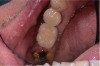
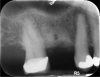
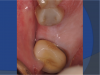
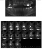
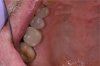
In this case, the patient’s right maxillary first molar had been extracted, and the site was grafted. The periapical radiograph taken after 6 months of healing indicated the presence of dense bone (Figure 11). There was also ample attached mucosa (Figure 12). Impressions were taken, a diagnostic cast was made, and a wax-up of the restoration was placed in the model (Figure 13). To make the radiographic guide for this case, a silicone putty index was created over the diagnostic wax-up, as described earlier. A panoramic radiograph and a CBCT scan (Figure 14) were taken with the radiographic guide in place; the guide post in the index can clearly be seen.
After merging the digitized cast and CBCT scan data, the dimensions of the site were evaluated. Almost 11 mm of bone was present below the maxillary sinus, and the width of the site was 8.5 mm, which was sufficient space to enable creation of a screw-retained restoration. To facilitate the screw access, a decision was made to position the implant slightly lingually, while maintaining the implant within the housing of buccolingual plate.
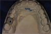
Additional planning steps are evident in Figure 15. The soft-tissue configuration has been sketched in white, with the planned implant position indicated in blue. The implant appears to avoid any impingement on the sinus floor or the adjacent roots, which are straight and parallel. The diameter of the planned implant was 4.8 mm, and the length was 8 mm. Although the length was somewhat short, the width was expected to compensate for that, along with the fact that a two-stage protocol would be followed. The planning procedures also provide valuation information about the drilling procedures for the osteotomy preparation.
Based on this plan, a 3D surgical guide was printed (Figure 16), with the position of the implant placement sleeve slightly tipped to the buccal. Openings in the guide helped to assure proper seating.
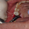
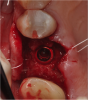
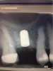
For the surgery, a crestal incision was made, and a flap was reflected to the subperiosteal area to expose the bone. Because of the tight, firm quality of the gingiva, a suture was placed both lingually and buccally to pull the tissue out and ensure that it would not get caught underneath the surgical guide and compromise proper seating. Following the guided surgical procedure, the recommended drilling series was followed to create the osteotomy and insert the implant (Figure 17 and Figure 18), and a postoperative radiograph was taken (Figure 19). A cover screw was attached to the implant, and the flap was sutured over it. The patient was allowed to heal with the implant submerged for 4 months.
After the healing period, the patient returned to begin the restorative phase of treatment. Although a traditional analog impression was made, an alternative is to use an intraoral scanner with a scan body; the entire workflow can then be digital. The favorable position of the platform-switched implant in this case promised to allow for an esthetic emergence profile, and a final decision was made to restore the implant with a screw-retained, all-zirconia, titanium-based restoration. The crown was milled in a CAD/CAM process, with the implant access opening just slightly to the lingual, which was an ideal position. The crown contour followed the angle of the adjacent teeth, which was a natural and comfortable position for the patient.
Figure 20 and Figure 21 show the definitive restoration on the cast, where the contacts were adjusted. The crown was then placed on the implant, where the contacts were adjusted again to hold the shimstock very lightly. After the contacts were confirmed to be favorable, holding dental floss well, the occlusion was adjusted. In general, the author prefers for the occlusion to be slightly lighter than on the natural teeth to avoid occlusal overload on the implant. It should be possible to pull a little shimstock through the occlusal contacts; any excursive contacts that might harm the implant also should be avoided.
The final restoration (Figure 22) was first glazed, and only at the conclusion of that process was the titanium base cemented. The screw-access hole was covered with Teflon tape and sealed with composite.
Hybrid Screw-Cementable Restorations
A hybrid screw-cementable approach to implant retention has been discussed for almost 20 years.7 This method is appropriate for situations in which cementation is desired to ensure proper seating and create an optimal emergence profile but retrievability of the restoration also is a goal.17 Such a restoration can be cemented intraorally after proximal contact and occlusal contact adjustments, similar to a cement-retained crown, or it can be cemented extraorally to avoid the possibility of cement retention below the gumline.
The following case illustrates use of this approach.
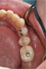
The case required placement of a tissue-level implant to restore the patient’s right mandibular first molar. A custom titanium abutment was fabricated with the margins just 0.5 mm above the gingiva to ensure that the area would be free of any retained cement (Figure 23). Figure 24 illustrates how the screw-access hole of the custom abutment was positioned slightly to the buccal. A decision was made to create a PFM crown that would be cemented to the custom abutment. However, the entire restoration would be screw-retained for future retrievability. The PFM that is fabricated for this type of restoration is a very thin coping that does not require a lot of space, is lightweight, and avoids a costly laboratory bill.
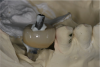
With a guide pin in position to prevent any cement from getting into the screw-access hole, the custom abutment was seated on the implant analog in the model, and the PFM restoration was cemented onto it with a non-eugenol resin-based implant cement (Figure 25). Proper seating was confirmed, and the contacts were adjusted. The restoration was removed from the implant analog, excess cement was cleaned off, the guide pin was removed, and the cement-retained restoration was then seated on the implant in the mouth and tightened to 35 Ncm. Although it is easier to cement the PFM restoration to the custom abutment on the model, alternatively, it is possible to insert the custom abutment in the mouth and cement the crown to it, making sure that the orientation is correct and the contacts are optimal. The abutment and crown assembly is then removed for cement removal and then reseated in the mouth (Figure 26).
Use of this type of cement depends in part on the height of the custom abutment. If the tooth and abutment are tall, the height will provide good mechanical retention, and very little cement will be required. For a short custom abutment, more cement should be used. The author recommends placing the cement on a mixing pad and then applying a thin layer to the internal area of the restoration, avoiding getting it too close to the margin. The restoration can then be seated, applying pressure. Any excess cement should then be removed. The cement can also be used for three- to five-unit fixed dental prostheses on multiple implants. The multiple-unit restorations can then later be removed for periodic inspection.
Summary
Important clinical points required for proper implant planning include consideration of the patient’s medical and oral hygiene history and thorough intraoral and extraoral examinations. This article has presented a protocol for creating a radiographic guide to be worn during CBCT scanning and a surgical guide to ensure that the implant placement and angulation will enable achievement of the desired restorative results. Three cases also were presented illustrating cement-retained, screw-retained, and hybrid “screwmentable” retention of single-implant restorations.
DISCLOSURE
The author has no disclosures to report.
ABOUT THE AUTHOR
Amerian D. Sones, DMD, MS
Faculty, Texas A&M University, College of Dentistry, Dallas, Texas; Diplomate, American Board of Prosthodontics
REFERENCES
1. Adell R, Lekholm U, Rockler B, Brånemark PI. A 15-year study of osseointegrated implants in the treatment of the edentulous jaw. Int J Oral Surg. 1981;10(6):387-416.
2. Hebel KS, Gajjar RC. Cement-retained versus screw-retained implant restorations: achieving optimal occlusion and esthetics in implant dentistry. J Prosthet Dent. 1997;77(1):28-35.
3. Wilson TG Jr. The positive relationship between excess cement and peri-implant disease: a prospective clinical endoscopic study. J Periodontol. 2009;80(9):1388-1392.
4. Padron FJ, Rubinstein S, Fujiki T. Cement- vs. screw-retained implant-supported restorations. Inside Dentistry. 2014;10(3):37-41.
5. Shapoff CA, Lahey BJ. Crestal bone loss and the consequences of retained excess cement around dental implants. Compend Contin Educ Dent. 2012;33(2):94-101.
6. Shadid R, Sadaqa N. A comparison between screw- and cement-retained implant prostheses. A literature review. J Oral Implantol. 2012;38(3):298-307.
7. Chee WW, Torbati A, Albouy JP. Retrievable cemented implant restorations. J Prosthodont. 1998;7(2):120-125.
8. Lee A, Okayasu K, Wang HL. Screw- versus cement-retained implant restorations: current concepts. Implant Dent. 2010;19(1):8-15.
9. Guichet DL, Caputo AA, Choi H, Sorensen JA. Passivity of fit and marginal opening in screw- or cement-retained implant fixed partial denture designs. Int J Oral Maxillofac Implants. 2000;15(2):239-246.
10. Misch CE. Screw-retained versus cement-retained implant-supported prostheses. Pract Periodontics Aethet Dent. 1995;7(9):15-18.
11. Strong SM. What’s your choice: cement- or screw-retained implant restorations? Gen Dent. 2008;56(1):15-18.
12. Agar JR, Cameron SM, Hughbanks JC, Parker MH. Cement removal from restorations luted to titanium abutments with simulated subgingival margins. J Prosthet Dent. 1997;78(1):43-47.
13. Weber HP, Kim DM, Ng MW, et al. Peri-implant soft-tissue health surrounding cement- and screw-retained implant restorations: a multi-center, 3-year prospective study. Clin Oral Implants Res. 2006;17(4):375-379.
14. Sones AD. Complications with osseointegrated implants. J Prosthet Dent. 1989;62(5):581-585.
15. McGlumphy EA, Mendel DA, Holloway JA. Implant screw mechanics. Dent Clin North Am. 1998;42(1):71-89.
16. Jemt T, Laney WR, Harris D, et al. Osseointegrated implants for single tooth replacement: a 1-year report from a multicenter prospective study. Int J Oral Maxillofac Implants. 1991;6(1):29-36.
17. Callaghan M, McKeon P. The screwmentable. OralHealth. July 13, 2016. http://www.oralhealthgroup.com/features/the-screwmentable/. Accessed August 23, 2016.