You must be signed in to read the rest of this article.
Registration on CDEWorld is free. You may also login to CDEWorld with your DentalAegis.com account.
The increased use of dental implants may be attributed to five factors: demographics of an aging population1; the restorative standard of care change from removable and fixed bridges to dental implant-supported prostheses2,3; improved implant prosthetic designs; micro- and nano-roughened implant surfaces4; and less traumatic surgical techniques. The trend towards minimally invasive surgery follows those in medicine and other aspects of dentistry. These techniques are still evolving, but are less traumatic and have shorter healing times, less morbidity, and higher patient acceptance than conventional surgery. Another result of newer techniques is decreased patient resistance to these surgical procedures, creating more candidates for treatment. A minimally invasive technique that also preserves more native bone is especially advantageous in the edentulous posterior maxilla, where bone quality is generally poor5 and the bone height is often reduced by sinus pneumatization and alveolar resorption.6,7 Alveolar resorption in these areas is further increased over time with soft-tissue bearing maxillary removable prostheses.8
Osteotome Sinus Lift Procedure
The osteotome sinus lift procedure was originally developed as a less invasive bone augmentation approach than the traditional sinus window approach (Caldwell-Luc) so that implants could be placed into the maxillary posterior area with a reduced bone height. It was first described by Summers9 as a technique to augment the maxillary sinus and place implants in areas where there was 6 mm or more of native bone. In that technique, a crestal approach was used instead of the classic lateral window approach. The Schneiderian membrane was repositioned apically with bone grafting materials, including autogenous bone, using osteotomes. The dental implant was placed at the same appointment, decreasing the number of surgical visits required. A number of articles have been published on modifications of this technique.10-16
The technique described in this article is a modification of the classic osteotome sinus augmentation procedure. This technique requires less native bone height (less than 5 mm), is less traumatic, does not require infracturing of bone, uses non-autogenous material in the graft with calcium sulfate to accelerate bone growth, and includes a bone-level tapered implant design with platform shifting. Cone-beam computed tomography (CBCT) verification is also presented.
Clinical Procedure
Membrane Exposure
This modified technique begins with patients being screened preoperatively for local or systemic factors that could interfere with sinus augmentation or implant placement. Any history of chronic sinusitis requires medical clearance. Any systemic condition contraindicating implant placement would also be a contraindication to this procedure. Measurements are made using periapical radiographs; however, panographic film and/or CT scanning are advisable and provide additional valuable diagnostic information. The minimum height of bone below the sinus required for this technique is 2 mm to 3 mm, which is enough bone to get good fixation of the implant.17 Pre- and postoperative antibiotics are started on the day of surgery and would include a 1 g loading dose of amoxicillin, followed by 500 mg tid for 7 to 10 days. If there is an allergy to amoxicillin, alternatives include clindamycin 300 mg, followed by 150 mg qid for 7 to 10 days, or azithromycin starting the day of the surgery. A surgical stent is helpful for ideal implant placement, particularly if there is no tooth distal to the implant site. Raising the floor of the sinus is also easier if the floor is concave.
There are two options regarding surgical access. A standard full-thickness flap with a crestal incision can be performed to gain access to the bony ridge, and the flap elevated to observe the facial and palatal contours of the bone. The other option for access is a gingival punch technique. To aid in positioning of the punch, a small incision can be made where the center of the punch will be used and a small piece of gutta percha placed inside this small incision. A radiograph can then be taken to verify positioning. With this punch technique, it is helpful to use a small chisel or scaler after making the punch and removing tissue to internally loosen the circumferential tissue to get a better evaluation of the bony architecture. A 5.75 mm ridge thickness is the minimal width required to use a 3.75-mm implant. (With this diameter, an implant made of titanium alloy is recommended, because alloy is stronger than commercially pure titanium.)
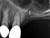
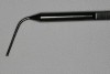
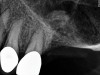
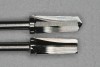
As with implant placement in general, use of a round bur is the first step in forming the osteotomy. As described above, to get verification of positioning—especially if a surgical stent is not used—a small piece of gutta percha can be placed inside this small osteotomy and a radiograph taken (Figure 1), after which the gutta percha is removed. The next step is the most critical, as it involves exposing the Schneiderian membrane. A 2-mm twist drill is used at a speed not exceeding 250 rpm, using a very light touch. Because the bone quality in the maxillary posterior is generally poor, it is usually easy to feel when the medullary bone has been breached and the dense cortical bone of the floor of the sinus has been reached. The cortical plate of the floor of the sinus should have been carefully measured with periapical radiographs presurgically, but it is usually about 1 mm in thickness. The most important and technique-sensitive part of this procedure is breaching the cortical plate of bone lining the sinus without tearing the sinus membrane. With a solid finger rest, good control, very light drilling pressure, copious irrigation, and a slow drilling speed, a slight “give” occurs once this plate of bone is breached. The full width of the twist drill should not penetrate the sinus floor; otherwise, the membrane will be torn. If it is not clear whether the membrane has been exposed, a flat-ended implant probe (Figure 2) can be used by inserting it into the osteotomy and feeling for the slight “give” or movement of the membrane. If the surgeon is not sure if the membrane is exposed, a radiographic marker can be used (Figure 3). If the membrane is significantly exposed, however, a radiographic marker should not be used, as this can inadvertently tear the membrane. The patient should also be warned not to bite down on the marker during the radiograph to avoid a membrane tear, and floss must be attached to the marker, so it can be retrieved if necessary.
Once a portion of the membrane is exposed, the osteotomy is widened to 2.8 mm with very light pressure, again not exceeding 250 rpm, stopping at the base of the osteotomy. The membrane should be verified with a blunt implant probe (eg, MT-BTI10, Implant site depth probe, MIS Implants Technologies Inc., www.mis-implants.com) (Figure 2), and a piece of collagen sponge or collagen membrane should be placed in the apical part of the osteotomy.
The next step is bone augmentation. A blunt implant probe is critical because a normal periodontal probe or rounded implant probe can tear the membrane. If the membrane integrity has been violated to the point that it cannot be felt with the probe at any part of the procedure, there are then two different options:
1. The first option is that the surgeon can change to a traditional standard sinus lift approach to gain access to the Schneiderian membrane (Caldwell-Luc), in which case the perforation will be small, and after standard membrane elevation, a piece of collagen membrane can be placed on the inner surface of the membrane; then the standard bone packing procedure can proceed.
2. The other option is to suture the flap back into place and inform the patient that the procedure will be resumed in approximately 6 to 8 weeks, at which time the soft tissue in the osteotomy can be used to help lift the sinus membrane using a sharp dissection of the portion of the flap that is over the osteotomy. In this way the Schneiderian membrane is not torn when the flap is raised. If a flapless approach was used, a coronally positioned flap should be raised and positioned to cover the osteotomy to avoid forming a postoperative sinus-antral opening.
Bone Augmentation
A composite bone graft material (described in detail below) has two main advantages over using just autogenous bone. First, it does not require a second surgical site to obtain the bone. Second, because the material is “off the shelf,” there is a plentiful supply. The surgeon’s choice of the bone grafting material is critical due to the minimal amount of native bone.
Because maximizing osteogenesis is important to this technique, calcium sulfate (eg, BondBone®, MIS Implants Technologies Inc.) should be added to the graft material in combination with demineralized freeze-dried bone allograft (DFDBA) and mineralized bone (freeze-dried bone, deproteinized bovine bone, etc). Calcium sulfate has been shown to increase the rate of angiogenesis18,19 in grafted material, as well as increase the turnover rate of DFDBA in extraction sockets.20 Another study using meta-analysis21 to examine different grafting materials with the lateral window approach reported that DFDBA, in combination with hydroxyapatite, had the highest implant survival rate, although no studies in the literature report this combination with calcium sulfate with osteotome sinus augmentation. Calcium sulfate alone, however, has been used as the sole grafting materials in the sinus with a lateral window approach, with good results.22 Calcium sulfate also physically lies in-between the particulate bone graft materials when used as a component of a composite graft and has a resorption rate of approximately 3 to 4 weeks.23
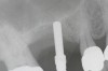
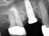
Because the bone grafting materials used in this technique need physical stability during healing to support the raised membrane, there is a high probability that significant shrinkage of the graft will occur as it heals and matures if only non-demineralized material is used. For these reasons, a composite graft using calcium sulfate, DFDBA, and mineralized particulate bone is used. A 50:50 mixture by volume of mineralized bone grafting material and DFDBA is used, to which approximately 40% calcium sulfate by volume is added. A higher percentage of calcium sulfate is used relative to that described for composite grafting in other uses, because some of the calcium sulfate will wash out during bone packing. Another advantage to this composite graft is that it is not as radiopaque as a purely mineralized graft. This allows radiographic monitoring of the bone healing around the implant, which can be used to time abutment placement on the implant. This is demonstrated in Figure 4 and Figure 5, which are radiographs taken on the day of the initial surgery showing the radiographic appearance of the composite graft, implant, and graft, and in Figure 6, a 5-month postoperative radiograph with the abutment in place. The old floor of the sinus is indistinguishable from the area of new bone. Figure 7 shows a CBCT scan (Carestream Dental, www.carestreamdental.com) taken at 4 months with the old floor of the sinus indistinguishable from the new bone formed.
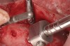
Magnification and fiber-optic lighting is critical; the authors assert that a surgical operating microscope gives the best visualization. There should be only enough composite bone graft material to fill about two-thirds of the osteotomy at each cycle, which, when brought to the site, can be condensed with the osteotome. The next step is to use the offset 2.8-mm diameter osteotome with a vertical stop (Figure 8). The vertical stop on the osteotome is critical to prevent the osteotome from entering the sinus cavity, thereby minimizing the chance of piercing the membrane. It should be initially set about 1 mm shy of the membrane. Very light malleting is then performed to push the bone graft against the membrane. If too much bone is used, or if the malleting is too aggressive, the chance of tearing the membrane increases. This is especially true when there is only about 2 mm to 3 mm of existing bone. By exposing the membrane before this step of the procedure, very little malleting or tapping force is required. The cycle of loading bone graft into the osteotomy and tapping it against the membrane with the osteotome is repeated several times gently, but after each tapping with the osteotome and mallet, the implant probe should be used for two reasons: first, to verify that the bone is in place and a membrane tear has not occurred; and, second, to gently wiggle the probe against the packed bone in all directions with very light pressure. This helps loosen the membrane circumferentially.
After about seven or eight cycles, a radiograph should be taken to verify the apical position of the sinus membrane (Figure 4). If the sinus has been raised at least 3 mm to 4 mm, the 2.8-mm twist drill should be used to remove the remaining bone at the base of the osteotomy. The osteotomy should then be widened to the final twist drill but not yet the last drill, which is the profile drill. This will allow for easier bone tapping into the sinus. The desired height of sinus membrane elevation should be such that there is about 1 mm to 2 mm of additional apical height above the implant to be placed. Usually a 10-mm implant length is sufficient. The design of the implant should have threads close to the coronal aspect of the rough surface for better initial fixation. When using a tapered implant design, the final drill is a tapered profile drill, which is the last step before placing the implant. Because it is slightly longer than the actual implant, its use could tear the membrane. To minimize the chance of tearing the membrane, a high-speed round bur and copious irrigation can be used to flatten the end of the tapered profile drill by about 1.5 mm (Figure 9) before its use. It should be used at less than 200 rpm with limited irrigation. The groove on the profile drill corresponds to the level of the bone when used. If there is minimal native ridge height, the drill should be used to a lesser depth than the groove to make sure that the site is not drilled too deeply.
The implant is then delivered and should be well stabilized in the bone. If there is any mobility of the implant, it can either be placed a little deeper (if there is enough native bone) or the implant can be removed and the procedure aborted, in which case it would be a two-stage procedure. This should rarely occur with the tapered designed implant, even with only 2 mm of native bone. Using a bone-level platform-shifting implant (or a tissue-level designed implant) is critical, as the hard and soft tissue will establish a biologic width. If an external hex type of implant is used and the shoulder is placed at the bone level, an expected bone loss of 1.5 mm to 2 mm will occur.24 Figure 10 shows proper bone-level implant depth placement with a platform-shifting design. In this case, a 3-mm healing abutment was placed at the time of surgery to avoid a secondary uncovering surgery, but an implant-level healing abutment could have been placed instead. As can be seen, there was only about 2 mm to 3 mm of native bone height. The membrane was raised about 8 mm to 9 mm. Comparing the radiograph on the day of surgery (Figure 10) to the 6-month postoperative radiograph (Figure 11) shows no loss of native bone, as well as the positive change in appearance of the grafted bone. The 3.5-month CBCT scan (Figure 12) shows good healing of the bone with no coronal bone loss. With minimal native bone present, as in this case, the use of a non-platform-shifting or non-tissue-level implant design could be problematic. After 1.5 mm to 2 mm of crestal bone loss, an external hex designed implant could develop instability with possible implant failure. If a non-tapered implant is used and bone loss occurs during healing, migration of the implant into the sinus could potentially occur. The surgeon can use either a healing abutment or implant-level closure screw over the implant shoulder. With patients who tend to use their tongues to explore or play with the area, or if the area is under a removable partial denture, a closure screw is recommended.
Primary closure is not required, although monofilament resorbable sutures are recommended to avoid bacteria wicking into the site. Standard postoperative instructions should be given to patients, including precautions regarding the sinus. Patients should be instructed not to blow their nose for 2 weeks. If they sneeze, it should be done with an open mouth.
Case 1
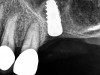
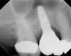
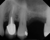
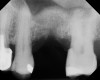
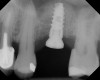
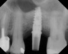
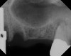
A 74-year-old man presented with only about 2 mm to 3 mm of native bone below the sinus in the No. 14 position (Figure 13). The composite graft used was an approximately 50:50 mixture of DFDBA (Bio-Oss®, Geistlich Biomaterials, www.bio-oss.com) with the addition of about 40% calcium sulfate by volume (Figure 14). The implant placed (Figure 15) was a 10-mm long, rough-surfaced, platform-shifting implant (tapered 4.2 mm to 2.8 mm), and the sinus was raised about 8 mm. The postoperative radiograph taken at 4 months (Figure 16) showed some shrinkage of the graft, but no demarcation of the old sinus floor in the area.
Case 2
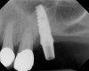
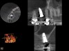
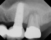
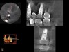
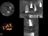
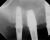
A 74-year-old male patient presented with about 4 mm to 5 mm of native bone in the No. 4 position (Figure 17). A composite graft, as described in Case 1, was used, as was the same implant type, but the implant was 11.5 mm in length with a taper of 5 mm to 4.2 mm. The approximately 16-month post-healed floor of the sinus was raised about 7 mm to 8 mm (Figure 18). The CBCT scan taken at 16 months postoperatively showed no change in appearance from the area of the old floor of the sinus to the new bone formed (Figure 19). Although it was endodontically involved, tooth No. 15 was not extracted, against professional advice. As can be seen in Figure 18, the No. 14 implant is acting as a bridge abutment.
Case 3
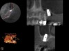
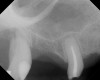
This patient was a 73-year-old man with only about 3.5 mm of native bone in the No. 3 site (Figure 20). The composite graft used here was a 50:50 mixture of DFDBA and deproteinized bovine bone mineral (Osteohealth, www.osteohealth.com) with approximately 40% calcium sulfate added. The implant was the same type and length as in Case 1 above. Figure 21 shows the area on the day of placement. In the CBCT scan on the day of placement (Figure 22), the native bone and bone graft were clearly discernable. However, the postoperative radiograph taken at 6.5 months (Figure 23) showed no marginal bone loss and a significantly denser appearance than when the graft was place. The membrane was raised about 7 mm to 8 mm. The final radiograph was taken after extraction of tooth No. 2 and after extraction of tooth No. 4 and immediate implant placement.
Discussion
The many advantages of the osteotome procedure include decreased morbidity, earlier restoration, and greater patient acceptance than the standard lateral window sinus augmentation procedure. As this technique has evolved, less native sinus bone is required to perform the procedure. Prior studies have demonstrated a greater chance of tear of the Schneiderian membrane when elevation of more than 4 mm is performed.25 This has led surgeons to perform a more aggressive lateral approach sinus graft when significant increase in vertical height is desired. In the past, “conventional” osteotome site preparation was undertaken when elevating the sinus between 2 mm and 4 mm.26 With the technique presented in this article, only 2 mm to 3 mm of native bone is required. This provides more options to the clinician and patient, as more patients who have less native bone in the sinus area can now be candidates.
This article also describes the advantages of the composite graft using calcium sulfate and DFDBA. There are many advantages when using a composite graft with these two materials.19,20,27 Although there is not yet histologic evidence to prove that calcium sulfate increases the turnover of DFDBA in an osteotome sinus augmentation procedure, there is evidence of this in other dental procedures,20,28 so it may also be an advantage of using DFDBA in the osteotome procedure. There is also radiographic evidence of this presented in this article. Abutment placement can generally be completed in about 4 to 6 months, depending on the radiographic appearance, the initial amount of native bone present, and the patient’s age. This can be contrasted to the standard lateral window augmentation approach, which would require about 6 to 9 months of healing before implant placement, then another 4 to 6 months of healing before abutment placement if standard grafting materials are used. If less mineralized material is used, however, there will be more vertical shrinkage of the graft during healing.
When using this technique in minimal native bone, a bone level or single-stage implant design is critical. If a two-stage design is used, it is essential to place the top of the implant at the crest of the bone. If two-stage design—but not platform-shifting design—is used and the implant becomes inadvertently exposed during healing, at least 2 mm of bone will be lost to establish biologic width. This can lead to implant loss or inadvertent implant float into the sinus. With a two-stage implant design, even if there is uneventful initial healing with no implant exposure, when the second-stage surgery occurs to place a transgingival healing cover screw, approximately 2 mm of bone will be lost to establish biologic width.28 If there were only 2 mm of native bone to start with, the implant would then be solely in grafted bone. A longer healing period would then be required until the implant could be restored. With a platform-shifting or single-stage implant, the biologic width is established coronal to the native bone, which is a distinct advantage. A tapered design has the advantage of increasing the primary stability of the implant at the time of placement.
Conclusion
As implant indications and usage increase, minimally invasive surgical techniques will continue to evolve. This article discussed new modifications in instrumentation, technique, and biomaterials used in the osteotome technique. Indications and usage of placing implants in conjunction with osteotome sinus augmentation when there is minimal native bone below the maxillary sinus were discussed and presented. There are distinct advantages to the patient and the clinician of a minimally invasive technique. Patient acceptance will continue to increase as healing time until restoration is reduced and morbidity is decreased. As with all new techniques, additional long-term studies should be performed to quantify successful outcomes.
ABOUT THE AUTHORS
David Anson, DDS
Private Practice, Beverly Hills, California
Robert Horowitz, DDS
Private Practice, Scarsdale, New York
REFERENCES
1. He W, Sengupta M, Velkoff VA, DeBarros KA. 65+ in the United States: 2005. Washington, DC: US Census Bureau, Current Population Reports, P23-209; 2005.
2. Curley AW. Dental implant jurisprudence: avoiding the legal failures. J Calif Dent Assoc. 2001;29(12):847-853.
3. Anson D. The changing treatment planning paradigm: save the tooth or place an implant. Compend Contin Educ Dent. 2009;30(8):506-520.
4. Cochran DL. A comparison of endosseous dental implant surfaces. J Periodontol. 1999;70(12):1523-1539.
5. Pietrokovski J. The bony residual ridge in man. J Prosthet Dent. 1975;34(4):456-462.
6. Pietrokovski J, Massler M. Alveolar ridge resorption following tooth extraction. J Prosthet Dent. 1967;17(1):21-27.
7. Misch CE. Treatment planning for edentulous maxillary posterior region. In: Misch CE, ed. Contemporary Implant Dentistry. St. Louis, MO: Mosby; 1993:241.
8. Atwood DA. Postextraction changes in the adult mandible as illustrated by microradiographs of mid-sagittal sections and serial cephalometric roentgenograms. J Prosthet Dent. 1963;13(5):810-824.
9. Summers RB. The osteotome technique: Part 3—Less invasive methods of elevating the sinus floor. Compend Contin Educ Dent. 1994;15(6):698-708.
10. Horowitz RA. The use of osteotomes for sinus augmentation at the time of implant placement. Compend Contin Educ Dent. 1997;18(5):441-454.
11. Fugazotto PA. Sinus floor augmentation at the time of maxillary molar extraction: technique and report of preliminary results. Int J Oral Maxillofac Implants. 1999;14(4):536-542.
12. Nkenke E, Schlegel A, Schultze-Mosgau S, et al. The endoscopically controlled osteotome sinus floor elevation: a preliminary prospective study. Int J Oral Maxillofac Implants. 2002;17(4):557-566.
13. Toffler M. Site development in the posterior maxilla using osteocompression and apical alveolar displacement. Compend Contin Educ Dent. 2001;22(9):775-790.
14. Cosci F, Luccioli M. A new sinus lift technique in conjunction with placement of 265 implants: a 6-year retrospective study. Implant Dent. 2000;9(4):363-368.
15. Davarpanah M, Martinez H, Tecucianu JF, et al. The modified osteotome technique. Int J Periodontics Restorative Dent. 2001;21(6):599-607.
16. Fugazzotto PA. The modified trephine/osteotome sinus augmentation technique: technical considerations and discussion of indications. Implant Dent. 2001;10(4):259-264.
17. Peleg M, Garg AK, Mazor Z. Predictability of simultaneous implant placement in the severely atrophic posterior maxilla: A 9-year longitudinal experience study of 2132 implants placed into 731 human sinus grafts. Int J Oral Maxillofac Implants. 2006;21(1):94-102.
18. Strocchi R, Orsini G, Iezzi G, et al. Bone regeneration with calcium sulfate: evidence for increased angiogenesis in rabbits. J Oral Implantol. 2002;28(6):273-278.
19. al Ruhaimi KA. Effect of adding resorbable calcium sulfate to grafting materials on early bone regeneration in osseous defects in rabbits. Int J Oral Maxillofac Implants. 2000;15(6):859-864.
20. Vance GS. Greenwell H, Miller RL, et al. Comparison of an allograft in an experimental putty carrier and a bovine-derived xenograft used in ridge preservation: a clinical and histologic study in humans. Int J Oral Maxillofac Implants. 2004;19(4):491-497.
21. Tong DC, Rioux K, Drangsholt M, Beirne OR. A review of survival rates for implants placed in grafted maxillary sinuses using meta-analysis. Int J Oral Maxillofac Implants. 1998;13(2):175-182.
22. De Leonardis D, Pecora GE. Augmentation of the maxillary sinus with calcium sulfate: one-year clinical report from a prospective longitudinal study. Int J Oral Maxillofac Implants. 1999;14(6):869-878.
23. Sottosanti J. Calcium sulfate: a biodegradable and biocompatible barrier for guided tissue regeneration. Compend Contin Educ Dent. 1992;13(3):226-234.
24. Weng D, Nagata MJ, Bell M, et al. Influence of microgap location and configuration on the periimplant bone morphology in submerged implants. An experimental study in dogs. Clin Oral Implants Res. 2008;19(11):1141-1147.
25. Reiser GM, Rabinovitz Z, Bruno J, et al. Evaluation of maxillary sinus membrane response following elevation with the crestal osteotome technique in human cadavers. Int J Oral Maxillofac Implants. 2001;16(6):833-40.
26. Alghamdi AS. Osteotome maxillary sinus lift using bovine bone and calcium sulfate: a case series. Clin Implant Dent Relat Res. 2011. doi:10.1111/j.1708-8208.2011.00420.x. [Epub ahead of print]
27. Anson D. Maxillary anterior esthetic extractions with delayed single-stage implant placement. Compend Contin Educ Dent. 2002;23(9):829-848.
28. Mazor Z, Mamidwar S, Ricci JL, Tovar NM. Bone repair in periodontal defect using a composite of allograft and calcium sulfate (DentoGen) and a calcium sulfate barrier. J Oral Implantol. 2011;37(2):287-292.